Lightning phenomenon and characteristics
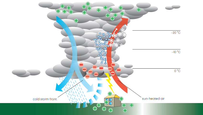
Since the experiments performed by B. Franklin, Romas and other lightning researchers we know that lightning is a physical phenomenon. It is created in thunderstorm cells. The cold storm front, which penetrates a hot area, forces the warm and humid air to rise. Temperature decreases with altitude and the water vapor condenses to small water droplets. This process is accompanied by the creation of heat which accelerates the air current. Reaching altitudes with subzero temperature, the water drops freeze to ice crystals. Again heat is produced simultaneously. The air speed increases once more – reaching a velocity of several hundred km/h – and propels the small ice particles to higher altitudes of up to 12 km. The growing ice crystals convert to hail stones which fall down due to their weight or remain in certain balanced positions. This causes electrons being stripped from the ice crystals. As a result of this process, charges are separated across a wide surface area. With field strengths of several 100 kV/m, discharges may be triggered in the form of cloud-to-cloud or cloud-to-earth lightning strokes, and in rare cases even as earth-to-cloud lightning.
Creation and threat of lightning
Strokes of lightning kill more people in Europe and North America each year than floods or tornados, causing billions of dollars in damage. The number of lightning-induced forest fires throughout the world alone runs to more than 10 000 annually. The electrical charge of a lightning stroke may exceed 100 As. It is discharged to the earth within 10 to 100 ms. The temperatures created in the lightning channel are higher than those on the sun’s surface. The air is heated so quickly that it expands with the
force of an explosion. The resulting sound waves can be heard as «thunder» as far away as 20 km. Lightning flashes may be as long as 50 km, but are only a few millimeters thick.

Thunderstorms occur most frequently in the tropical and subtropical belts surrounding the earth, where the temperatures and the air humidity are very high. At any given time, almost 2000 thunderstorms are in progress on earth, and every 1/100 second or 6000 times a minute a bolt of lightning strikes the earth. For many reasons the world is mapped concerning thunderstorm days – or the ground flash density (GFD) maps – and number of hits per area (square miles, square km, etc.). Also, satellite flash event maps are available.

In the USA alone, lightning strikes 40 million times each year. Its occurrence in the USA is greatest within a 100 kilometre wide strip crossing the state of Florida, called «lightning alley». In this area, thunderstorms can be observed on 90 days every year.

Such maps are an important tool to determine the hit risk for a certain location. But for a final conclusion a lot more factors have to be considered, and the calculation models consist of complicated formulas. Considerations are altitude, the height of the building, the surrounding profile, buildings in the neighbourhood, the distance to water, earth material and even if a lightning protection system is installed, to name only a few of them. In many cases – especially in the areas of lower altitude, the more northern and southern regions of the world – the theoretically calculated hit risk might look negligible. But hot spots of many countries can have multiple GFD values compared to average (e.g. Germany with more than tenfold values). Network operators have further to multiply the single BTS hit risk by the number of their sites. IEC 62305 provides a calculation formula for a rough estimation.
Interferences of close by hits, which can easily outnumber those of direct ones, have also to be considered.
The lightning hazard to electric and electronic equipment consists in the interferences of direct lightning current injections and high surge voltages induced by the electromagnetic field of nearby lightning channels or down conductors. The damage caused depends on the energy involved and on the sensitivity of the electronic systems. The electric surge pulse generated by lightning is called LEMP (Lightning Electromagnetic Pulse).
Lightning research has produced a large number of suitable protective measures that are reflected in international and national safety standards. These instructions and recommendations for the installation of lightning protection systems together with the application of HUBER+SUHNER lightning EMP protectors provide a high degree of safety for electronic equipment.
The installation of a lightning EMP protector costs only a fraction of today’s transceiver equipment. In the case of damage by EM interference in general natural, but also man-made the repair of the equipment but also the loss of revenue and good reputation due to downtime have to be considered.
All in all, there is not left much choice to an operator of mobile communications or other wireless services than to establish the best protection available.
Electrical specifications and effects of earth lightning
Here, we will only consider cloud-to-earth lightning, which has the greatest damage potential. This type of lightning is divided into positive and negative lightning, depending on the polarity of the cloud charge.
Positive cloud-to-earth lightning is the most critical, due to the duration of the lightning current pulse. With a maximum current of several 10 kA, it may last longer than 2 ms. The electrical charge is typically higher than 50 As.
Negative cloud-to-earth lightning starts with a lightning current pulse whose maximum amplitude amounts also to several 10 kA, but lasts merely 1/10 of the time of a positive one. Its peculiarity lies in the subsequent smaller multiple discharges, which may result in a total duration of the lightning of over one second and a total electrical discharge of over 100 As.
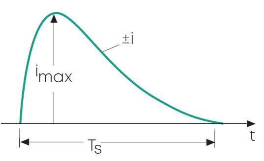
Pattern 1
Positive or negative lightning current pulse of several 10 kA and less than 2 ms duration (TS).
Pattern 2
Positive or negative lightning current pulse as pattern 1, with subsequent long-duration current of about 100 A during a period of less than 500 ms (TI).

Pattern 3
Sequence of negative lightning currents with a first lightning current pulse according to pattern 1 followed by subsequent lightning currents up to 10 kA. The break time between the lightning current pulses are shorter than 100 ms (TP).

Pattern 4
Sequence of negative lightning currents according to pattern 3, with integral long-duration current according to pattern 2.

On the basis of these lightning current patterns, CIGRÉ and IEC 62305 defined 3 groups of laboratory-simulated lightning currents:
Group 1: first stroke
Lightning current of positive or negative polarity, first stroke– wave form 10/350 μs

Group 2: subsequent stroke
Lightning current of negative polarity, subsequent stroke– wave form 0.25/100 μs

Group 3: long stroke
Lightning current of positive or negative polarity, long-duration stroke – Tlong = 0.5 s.

The most important parameters of lightning are the following:
- Lightning current amplitude ‘i’ determines the resistive effects mentioned below
- Average steepness of the lightning current di/dt determines the resistive and magnetic coupling effects mentioned below.
- Total charge: Q = ∫i · dt (unit As or C), determines the energy release/conversion at the hit point
- Specific energy (action integral): W/R = ∫i2 · dt (unit MJ/Ω or k2s), determines all heating and electrodynamic effects along the down-conducting path.

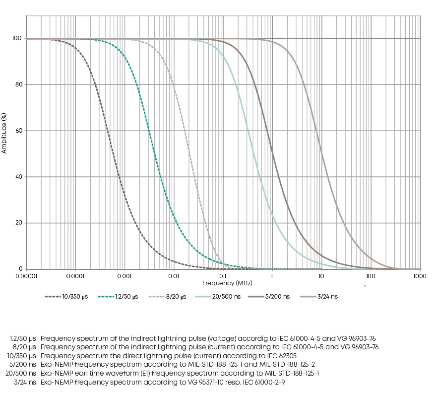
The frequency spectrum of the lightning electromagnetic pulse (LEMP) is also of interest, especially for RF applications. It reaches several 100 kHz (NEMPs about a thousandfold). This is important for certain lightning protection solutions in RF engineering applications described above.
The diagram shows that a 10/350 μs test pulse is a good match to a first-stroke of lightning. This is considered in IEC 62305, protection against lightning. Therefore, it is most suitable to test protective devices. HUBER+SUHNER test their lightning EMP protectors according to this pulse regarding the lightning current resistivity (also called current handling capability).
IEC 61000–4–5 defines a combined 1.2/50 μs voltage and 8/20 μs current test pulse for surge protective devices to determine their protection performance. Despite its relevance for general induction and power-switching interferences, this pulse is used for the description of the protection quality also of lightning EMP protectors worldwide. Protection performance data show residual pulse values as a result of a 1.2/50 μs; 8/20 μs combination generator pulse.
Coupling effects of lightning into systems
Resistive coupling
Partial lightning currents are coupled into all objects, which are electrically connected to the lightning path.
This results in:
Earth potential rise (of the transmitter or building), which is the voltage drop over the earth resistance caused by the lightning current amplitude
UE = i ・ RE
Assuming realistic values of i = 100 kA and RE = 10 Ω (a recommended maximum value), the result will be UE = 1000 kV(!) of potential rise against far-earth (which is the potential of all connected power supply, data and telephone lines).
Voltage drops over inductances, as each conductor provides, caused by the average steepness of the lightning current
UD = LD · di/dt.
- Assuming realistic values of subsequent lightning current pulses with di/dt = 100 kA/μs and LD = 10 μH (which is true for a down-conductor length of 10 m along a building or mast, 1 μH/m solid conductor), the result will be UD = 1000 kV (!) potential rise at the top against the ground of a structure.
- Longitudinal voltages over screened and coaxial cables.
- In general potential differences in electronic equipment.

Magnetic field coupling
The lightning current of near-hits or even a down-conducted one of the existing LPS (Lightning Protection System) induces surge currents and voltages in any effective electrical loop. This is determined by the average steepness of the lightning current as well and follows the formula:
U = –M · di/dt (M for mutual inductance)

Electric field coupling
The effects of the high and changing electrical field strength, right before the hit occurs, is normally negligible when considering a minimum of protection measures.
Protection against electromagnetic fields (LEMP/NEMP/HEMP)
Sensitive and safety related systems shall be protected from the negative effects of electromagnetic fields such as nuclear electromagnetic pulse (N)EMP. The extremely short rise and fall times of only a few nanoseconds (ns) and huge field strength up to some 10 kV can couple amounts of energy into systems which is far in excess of peak parameters of modern electronics. Irreversible damage and blackout of the systems is the inevitable result. Modes of entry are through antennas, transmission and utility lines as well as through direct penetration of shields and enclosures.
Lightning (LEMP) represents a threat of similar importance. Rise as well and fall times of a LEMP are longer when compared with a NEMP. The field strength is decreasing rapidly already within small distances from the striking point. However, the threat represented by lightning is not just due to induction effects. A direct stroke with peak currents ≥100 kA represents an additional threat.
The following graph shows the frequency response and the relative amplitude of various standardised (N) EMP and (L)EMP pulses.
Shielding encompasses all measures to attenuate the (N) EMP fields within a specially protected area or room. Such areas can be, bunkers, fix installed containers, vehicles or equipment chassis all built as Faraday cage.
According to MIL-SDT-188-125 part 1 and part 2, the screening efficiency of a metallic enclosure (Faraday cage) shall achieve a minimum level of 80 dB for frequencies ≥ 10 MHz.

But, the entire system cannot be shielded since antennas, transmission lines or other collectors of EMP signals which must interface with the system equipment cannot be completely enclosed within a metallic shield. Any entry into an shielded room will have a negative impact on its screening effectiveness such that it becomes more difficult to meet the MILSTD-188-125 requirements. It is therefore of utmost importance that the installation of cable feed-troughs and (N)EMP protection components is carried out in a professional way which shall be in line with the latest EMI / EMC installation rules. In particular, the exclusive use of

cable feed-troughs and (N)EMP protection products which guarantee a screening efficiency >> 80 dB when installed is recommended.
When looking at a typical coaxial port of entry (PoE) (see picture below) the transition from the housing (outer conductor) to the wall of the faraday cage is essential. To reach a high screening effectiveness between the unprotected and the protected area of an installation this transition shall be realised with low-inductance and low-resistance. In addition it shall be ensured that these values will stay stable over the full lifetime of the system.

Lightning protection principles
Basic principles of lightning protection
To protect electronic equipment, several different aspects shall be considered. Well-proven basic principles are shielding (Faraday cage, armed concrete, screened cables), bonding and grounding. The basic idea is to protect equipment and people against lightning by conducting the lightning current to ground via a separate preferential solid path and reduce the electromagnetic field. Today a lot of international and national rules exist to employ all well-tried measures to protect life, structures and equipment.
Account shall be taken of the most important international standards, such as IEC 62305 protection of:
- Structures, including their installation and contents as well as persons
- Services, connected to a structure against lightning
and others. They all define the proper planning, installation and inspection of effective lightning protection systems (LPS). The entire installation is classified into different lightning protection zones (LPZ) according to IEC 62305:
LPZ 0A
The zone where a direct hit is possible and where objects shall be capable of carrying the full lightning current. Also, the un-attenuated electromagnetic field is very dangerous (lightning current test pulse of first stroke 10/350 μs).

LPZ 0B
The zone where a direct hit is not possible, but the unattenuated electromagnetic field is present (lightning current test pulse 10/350 μs). This zone is determined by the external lightning protection system consisting of the air termination, down conductor and earth termination system.
The transition between LPZ 0 and LPZ 1 is the most important one. At this point all crossing conductive parts shall be connected to the bonding bar. Signal and transmission lines have to be equipped with lightning protection devices which are able to carry partial lightning current (10/350 μs).
LPZ 1
The zone where a direct hit is not possible and the currents in all conductive components are lower than in LPZ 0A and LPZ 0B. In this zone, the electromagnetic field is attenuated according to the screening measures applied. RF, signal and supply lines leading into this zone should be protected by surge protective devices (8/20 μs). They may be based on a number of different operating principles.
If a further reduction of the current or of the electric field is necessary, additional subsequent zones shall be established (LPZ 2, etc.). Additional surge protective devices shall be applied at each zone transitition (e.g. LPZ 1 / LPZ 2 ....).
For optimum protection, all electric supply and signal lines should enter the protected area at one single place. At this point, they shall be connected to the bonding bar by surge protective devices. At every interface between one LPZ and the next, the potential equalization shall be established like this.
This classifies lightning EMP protectors to be a part of the bonding system. They provide basically an interference event triggered bonding for signal-carrying lines.
Special lightning protection principles for RF applications allow a continuous bonding of lines. The grounding shall always be in accordance with IEC 62305. The grounding of the installed lightning EMP protectors, their connections to the bonding bar of the structure or equipment have to be prepared very carefully to achieve the lowest possible resistance and inductance to ground (refer to section «application notes»).
Lightning current evaluation on an antenna site
Model base station antenna system
Direct and indirect lightning strokes are mainly accompanied by resistive and magnetic coupling processes of their electrical energy. Capacitve coupling effects of surge energy by the high and fast-changing electrical field just before the lightning stroke occurs are negligible, if the system is well bonded to earth (electrical charge equalization).
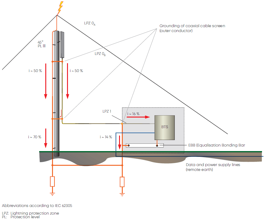
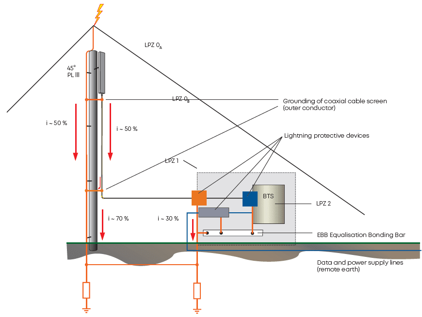
The following figure shows the lightning current distribution after a stroke into the antenna mast, respectively into the lightning protection system, caused by resistive coupling (equal current distribution as proven assumption according to IEC 62305, protection against lightning):
Current distribution without application of lightning EMP protection device
The following illustrates the resistive current distribution with lightning EMP protection device (e.g. quarter-wave shorting stub protectors) in detail:
Recommendations
Antennas or radio equipment should be located within the protection zone LPZ 0B of the external lightning protection system (LPS) according to IEC 62305 (protection against lightning: air-terminations, down-conductors and earth-termination). It is established as a 45° area downwards, related to the highest point of the air-termination as shown (assumption for a mast height up to 20 m and the protection level PL III according to IEC 62305).
LPZ 0B can principally be evaluated by the application of the sphere model according to IEC 62305, which allows to determine LPZ 0B for even more complicated structures.
Thus, the antenna or radio equipment is protected against direct lightning strokes with a probability of 90 % (PL III according to IEC 62305). But the electromagnetic field still acts unattenuated.
By the bonding of the antenna earth, radio equipment or upper-cable end screen to the down-conductor of the mast or the building surge voltages caused by magnetic coupling of direct and near lightning strokes into loops through earth can be avoided. If not done, the cables would have to be protected magnetically by iron tubes (which would also protect the inner conductor of coaxial cables).
Low frequency short-circuit connection of antennas against down-conductor (e.g. shunt-fed antennas or application of quarter-wave protectors). This helps avoiding a high surge voltage and therefore a possible undefined breakdown in the cable due to magnetic coupling of direct and near lightning strokes into loops across earth or remote earth). Direct-stroke-initiated partial lightning currents over the coaxial cable screen would otherwise cause together with the measure of the previous section undefined cable breakdown by the voltage drop against earth (as the inner conductor can have zero potential).
Longitudinal voltage on cables
Bonding of the cable screen to the down-conductor where it leaves the mast and with higher masts every 20 m. Thus, a potential equalization is achieved and the current over the cable screen to earth is reduced, as the down conductor has a lower impedance.
Application of coaxial cables with low DC resistance over inner and outer conductor (e.g. corrugated copper tube cables of as large size as possible – larger size means also higher dielectric withstanding voltage).
Application of reliable lightning EMP protection devices at the entry of LPZ 1. Thus, high partial lightning and induced currents (test pulse 10/350 μs according to IEC 62305) can be led to earth and over-voltages are reduced to a low level (potential equalization). Our supplier HUBER+SUHNER ran several tests to evidence the necessity of this measure. The cables RG 213, LMR 400, LDF 4-50A (1/2“) and LDF 5-50A (7/8“) were measured in the case of a resistive/inductive equipment input:
Measurement of the longitudinal voltage UL over the inner conductor
Here a test surge current of pulse shape 8/20 μs and 10/350 μs was sent into a 1 m piece of cable, inner and outer conductor connected at the input, output screen connected to earth and inner conductor to the oscilloscope input.Most important result: applying the 8/20 μs test pulse with 25 kA amplitude (half of the assumed load of the model antenna system, as 100 kA is the total lightning current according to PL
III) leads to a calculated (if a cable lengths of 10 m is assumed, for example) longitudinal voltage of:

The longitudinal voltage UL is proportional to cable length and partial lightning current amplitude!
Measurements with lightning currents of pulse shape 10/350 μs resulted as expected in longitudinal voltages of smaller amplitude (due to the lower rise time) but much higher pulse energy.
In case of DC selection over the coaxial cable to supply power for remote active electronic circuits in the antenna system, only gas discharge tube lightning EMP protectors can be employed. The residual pulse voltage behind the protector reaches up to several hundred volts over some nanoseconds, dependent on the selected gas discharge tube.
This requires additional protective devices for sensitive input circuits of electronic equipment. They can be located directly behind the gas discharge tube lightning EMP protector (or be a combined arrangement), if the equipment to be protected is nearby. Normally they should be placed at the entry of next protection zone, if a consequent zone concept is being followed (e.g. LPZ 2 – according to IEC 62305 every zone transition requires a separate lightning/surge protection device). The additional protector – here called surge suppressor due to its function – reduces the surge pulse voltage to a well-tolerated extent of only a few volts.
Coaxial cable

Loop voltage
A surge protective device is not only required due to the leftover residual pulse of the gas discharge tube lightning EMP protector, but also due to magnetic coupling into the possible loop which the antenna cable length between the lightning EMP protector and the equipment is part of (within zone LPZ 1). This is illustrated by the following:
Thirty meters of coaxial cable can form together with other signal, energy or bonding connections large induction circuits, which produce induced voltages of several hundred kV. Already the coaxial cable alone can act as an induction circuit for the strong magnetic fields of near lightning strokes, if not specially screened.
The induced voltage can be calculated with the following formula:
U = —M2 · di/dt M2 – mutual inductance of the loop
First partial lightning strokes show a current rate of change of up to 20 kA/μs, subsequent lightning strokes even of up to 200 kA/μs. The loop inductivity depends on the loop circumference and on the distance to the lightning stroke channel. Larger loops – e.g. 40 m – possess a M2 of about 1.5 mH at a distance of 10 m; with a distance of 1 m it increases to about 5 mH. Therefore, induced voltages ranging from 24 to 1000 kV can be produced.
Measures to minimise or compensate in-house lightning induction effects:
- Application of surge protectors and suppressors
- Short cable lengths
- Magnetic screening of cables (steel tubes/cable tunnels)
- Magnetic screening of the complete structure (Faraday shield)
- Distance to the possible lightning current channel as large as possible
- Hybrid earth-grounding system – single-point grounding, suitable line routing
Active electronic circuits in the antenna and additional line amplifiers have to be protected against surge pulses supplied from the connected coaxial cables (application of lightning EMP protectors and surge suppressors, high-pass not allowed with DC injection) and if possible also against magnetic coupling.
Concerning the otherwise occurring surge load refer to section application of reliable lightning EMP protection devices.
Active electronic circuits in the antenna and additional line amplifiers have to be protected against surge pulses supplied from the connected coaxial cables (application of lightning EMP protectors and surge suppressors, high-pass not allowed with DC injection) and if possible also against magnetic coupling. Concerning the otherwise occurring surge load refer to section application of reliable lightning EMP protection devices.
Installation of surge protective devices
Mounting and grounding recommendations
Our lightning EMP protector product range offers a high flexibility to meet mounting and grounding requirements in the field. Basically all mounting options are simultaneously suitable for grounding purposes.
We offer:
Bulkhead mounting

Screw mounting and bracket mounting
For best protection according to IEC 62305 when establishing protection zones consequently, it is recommended to deploy bulkhead mounting facilities. Thus the protectors can be installed as wall feed-through directly in the wall of the protected room. Doing so, the protectors should be installed consequently with the surge down conducting part – quarter-wave stub or gas discharge tube – outside of the protected area not to cause any unnecessary interference when dissipating surges. (This is reflected by the recommendations and definitions for «unprotected and protected side» of the device tables. Bulkhead mounting types and all high-pass filter types are marked accordingly.)
Our special bulkhead fixation design automatically enables a good long-term performance concerning a waterproof bulkhead transition, a corrosion-resistant contact area resulting in a stable contact to the bulkhead ground-plane, a low transition resistance and a vibration-resistant mounting of the protector (assuming the right sufficient torque forces are applied as shown in the supplied assembly instructions). This is true for standard sheet metal bulkheads such as stainless steel, copper or passivated aluminium with standard surface roughness and mounting holes according to the related product mounting hole specification.
For other mounting solutions care has to be taken for minimum interference. But generally all mounting options can carry the specified surge current when properly installed.
Grounding/bonding rules
For a good grounding respectively bonding the following has to be considered:
- During installation, the lightning EMP protection device must be connected with the central grounding point of the equipment EBB (Equalisation Bonding Bar) in a low-resistance and low-inductance way. Inadequate grounding concepts with ground loops, insufficiently sized grounding cables (smaller than 16 mm2/AWG 6), poor connections, etc., will increase the residual energy behind the lightning EMP protector as a result of high impedance (ohmic resistance by length and size and in addition inductance by length).
- The contact points of the ground connection shall offer good electrical conductivity (contact points shall be bare and free from dirt, dust and moisture).
- When threaded contacts are tightened (bulkhead grounding, GDT capsule holder), the minimum torque specified by the manufacturer shall be observed in order to minimize the contact resistance and to establish the effects mentioned above.
- The lightning EMP protection devices should wherever possible be located in the unprotected zone in order to rule out inductive interference.
- Our lightning EMP protection devices are characterised by their quick, easy, and at the same time reliable installation methods. The preferred variant is single-hole mounting as wall feed-through. They can be applied with round or with D- or H-shaped also called double-D-shaped mounting holes to prevent rotation. The mounting hole size is matched to the connector size and thereby to the forces acting on the device.
All this is crucial for achieving the lowest possible residual surge pulse (voltage and energy) on the protected side and with it keeping the interference load for the equipment as low as possible.
All of our lightning EMP protection devices are supplied along with an installation instruction describing the proper installation procedure.


